<center>06-GRIDGEN-TUTORIAL-矩形网格生成</center>
参考资料
waves-workshop-exercise-grigen.pdf;
也就是
COURS/WAVES_SHORT_COURSE/TUTORIALS/TUTORIAL-GRIDGEN里面的内容;
TUTORIALS目录的链接: https://pan.baidu.com/s/1S4qGSGGyJizdSAeFIerewA 密码: jpi1需要知道的一点是,TUTORIAL 是会更新的,下面是关于 2019 版本的;
- 链接:https://pan.baidu.com/s/1cpsjYBWf4IGzSo6Usom-iw
提取码:ne6g
–来自百度网盘

待解决问题
内容、知识点、创新点
目的
本练习的目的是向用户介绍名为 GRIDGEN 的网格生成软件。 它专为生成可用于 WAVEWATCH III 应用程序的网格而开发。 在这种情况下,我们将为南非创建一个网格,并使用分辨率为 0.5° 的全局网格定义其边界。
请注意:网格生成软件是一系列用于创建 ASCII 网格文件的 MATLAB 例程。 然后将这些文件提供给 ww3_grid 程序以生成特定的模型定义文件。 对 MATLAB 的一些有限的熟练程度将有助于跟随练习,但不是必需的。
GRIDGEN工作目录创建
创建一个 GRIDGEN 工作目录,假如为 work-griden ,在目录下打开终端,输入以下命令
## 将TUTORIAL-GRIDGEN文件夹放进word-griden ,用复制命令,因为TUTORIAL-GRIDGEN文件夹不大。
#  TUTORIAL-GRIDGEN具体的绝对路径需要更改;
cp   -r   /home/jincanliu/BaiduNetdiskWorkspace/WaveModel2/COURS/WAVES-SHORT-COURSE/TUTORIALS/TUTORIAL_GRIDGEN   .

## 将BATHY文件夹里的文件放进word-griden ,用软连接的形式创建,因为BATHY里的文件占用空间大。
#  建议用绝对路径创建软连接;
#  BATHY具体的绝对路径需要更改;
ln   -sf   /home/jincanliu/BaiduNetdiskWorkspace/WaveModel2/COURS/WATH_DATA/BATHY/*   /home/jincanliu/BaiduNetdiskWorkspace/WaveModel2/work-griden/TUTORIAL_GRIDGEN/reference/
现在可以进 ./TUTORIAL_GRIDGEN,开始操作。
TUTORIAL_GRIDGEN 目录


reference/coastal_bound_*.mat
海岸边界是Matlab二进制文件,以数据结构形式存储:加载这些文件中的任何一个都会为用户提供数据结构的形式。 只要使用相同的格式存储,用户就可以在此包中使用自己的沿海多边形。 对于每个边界,沿海多边形以逆时针模式定义,第一个点和最后一个点相同(以有效地关闭边界)。
reference/水深数据
该软件包提供的参考测深数据(在 “reference “文件夹中)是全球 ETOPO1和 ETOPO2数据文件,一个全球GEBCO数据文件和一个覆盖南非的区域SRTM文件。所有这些文件都是NetCDF格式的。
用户可以使用他们自己的水深数据集,但他们必须做以下两件事之一:… (看原文)
在这种情况下,用户必须注意尊重对水深数据集的以下主要要求:文件必须是NetCDF格式,扩展名为 “*.nc”,高程变量必须取决于 “longitude “和 “latitude “维度(无论其实际名称如何),经度和纬度变量必须作为1D数组提供,并具有 “实际范围 actual_range”属性。
关于水深数据本身,一般来说,有4种类型的水深参考:…(看原文)
对于GRIDGEN来说,水深数据集使用平均海平面(Mean Sea Level)作为水深参考水平是非常重要的(见OHI公约:http://www.iho.int/srv1/index.php?lang=en),因为WW3模型必须具有,与它将使用的海流和水位因素相同的水深参考。使用其他参照物会导致过高或过低估计海岸的潮湿点(例如,使用LAT会将一些点标记为 “干燥”,而实际上除了非常低的潮汐外,它们一直都在水下)。
水深的约定也必须是,深度是向下的负数。(否则,在GRIDGEN工具箱的第一步中创建的深度数组将返回错误的值)。
下面是一些可用的水深数据集及其分布国家和空间扩展的列表:
- etopo1 1’ US (global): https://www.ngdc.noaa.gov/mgg/global/global.html
- globe 30’’ US (global): https://www.ngdc.noaa.gov/mgg/topo/globe.html
- srtm 1’’ US (global): http://www2.jpl.nasa.gov/srtm/
- gebco 30’’ GB (global): http://www.gebco.net/data_and_products/gridded_bathymetry_data/
- shom 100m FR (France): data.shom.fr
如果你选择使用这些数据集,请确保它们符合上述要求。
grid创建:南非区域(一步一步实现,意义在于理解参数,不推荐在实际情况中使用)
00~~进入matlab环境
打开 matlab ,进入 work-griden/TUTORIAL_GRIDGEN/area/ 下(area文件夹是我自己创建的), 创建 south_Africa.m 文件,下面基本所有命令都放在这个 m 文件即可。
01~~设置网格基本参数&导入边界数据 bound
%% 这是 colormap 的设置
set(groot,'DefaultFigureColormap',jet)
%% 区域名称
area = 'south_Africa';
%% 路径设置(绝对路径 or 相对路径)
bin_dir = '/home/jincanliu/BaiduNetdiskWorkspace/WaveModel2/work-griden/TUTORIAL_GRIDGEN/bin'; % griden函数
ref_dir = '/home/jincanliu/BaiduNetdiskWorkspace/WaveModel2/work-griden/TUTORIAL_GRIDGEN/reference'; % 水深、边界数据
nml_dir = '/home/jincanliu/BaiduNetdiskWorkspace/WaveModel2/work-griden/TUTORIAL_GRIDGEN/namelist'; % ww3网格参数的预设置
data_dir = '/home/jincanliu/BaiduNetdiskWorkspace/WaveModel2/work-griden/TUTORIAL_GRIDGEN/data'; % 输出数据
%% 经纬度设置
dx = 0.125; dy = 0.125;
lon_west = 12;
lon_east = 23;
lat_south = -38.9;
lat_north = -27.2;
lon1d = (lon_west:dx:lon_east);
lat1d = (lat_south:dy:lat_north);
[lon,lat] = meshgrid(lon1d,lat1d);
%% 要允许从任何地方调用 GRIDGEN 函数,请将它们添加到路径中
addpath(bin_dir,'-END');
%% 加载边界mat文件。
% 用户可以从多个分辨率中进行选择,网格的生成速度越快,边界越粗。
% 最佳做法是构建具有完整分辨率边界的网格,即使这可能需要更多时间。
load([ref_dir,'/coastal_bound_full.mat']);
% 加载这个边界文件应该已经生成了一个名为 "bound "变量;
% 你可以通过输入不带分号的bound来检查结构的性质和阵列的大小;
bound
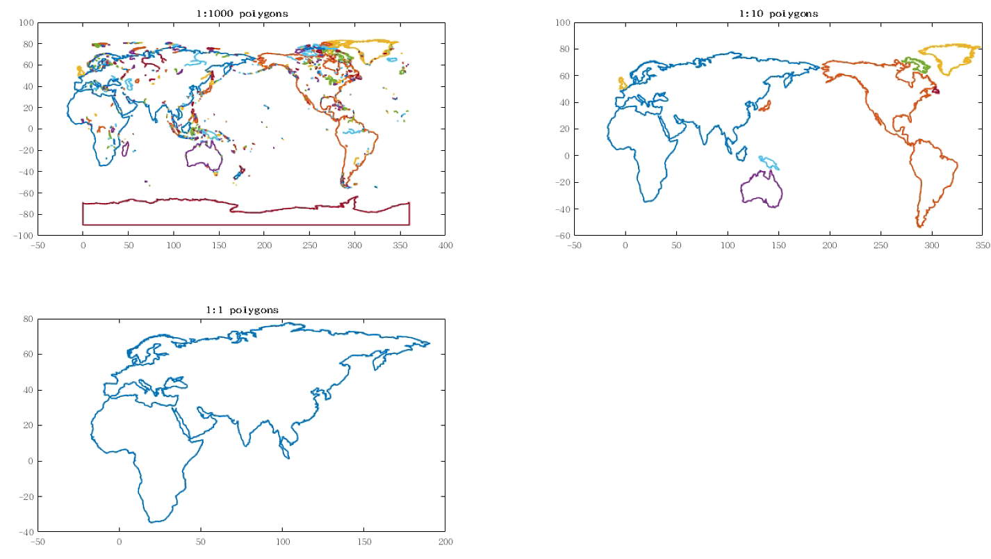
% bound 图形展示
figure('NumberTitle','off','Name','bound 图形展示','Color','w');
subplot(2,2,1);
for i = 1:1000 % 总共188603个polygons;
plot(bound(i).x,bound(i).y,'.','MarkerSize',0.5);
hold all;
end
title('1:1000 polygons')
subplot(2,2,2);
for i = 1:10
plot(bound(i).x,bound(i).y,'.','MarkerSize',0.5);
hold all;
end
title('1:10 polygons')
subplot(2,2,3);
for i = 1
plot(bound(i).x,bound(i).y,'.','MarkerSize',0.5);
hold all;
end
title('1:1 polygons')
02~~创建水深网格 depth&陆地-海洋掩码 m1 (LIM_BATHY)
%% 水深文件
ref_grid = 'gebco'; % Name of the file without the '.nc' extension
xvar = 'lon'; % Name of the variable defining longitudes in file
yvar = 'lat'; % Name of the variable defining latitudes in file
zvar = 'elevation'; % Name of the variable defining depths in file
%% 创建水深网格的参数设置
CUT_OFF = 0.0; % Cut-off depth to distinguish between dry & wet cells
% 小于0,'wet';大于0,'dry';
LIM_BATHY = 0.4; % Base bathymetry cells needing to be wet
% for the target cell to be considered wet.
DRY_VAL = 999999; % Depth value set for dry cells
%% 创建水深网格 depth
depth = generate_grid('rect',lon,lat,ref_dir,ref_grid,LIM_BATHY,CUT_OFF,DRY_VAL,xvar,yvar,zvar);
depth
% depth 的图形展示
figure('NumberTitle','off','Name',strcat(area,'的水深网格 depth 图形展示'),'Color','w');
d=depth;d(d==DRY_VAL)=nan; pcolor(lon,lat,d); shading flat; colorbar
%% 创建海陆掩码 m1
m1 = ones(size(depth));
m1(depth == DRY_VAL) = 0;
% m1 的图形展示
figure('NumberTitle','off','Name',strcat(area,'的海陆掩码 m1 图形展示'),'Color','w');
pcolor(lon,lat,m1);shading flat;caxis([0 3]);colorbar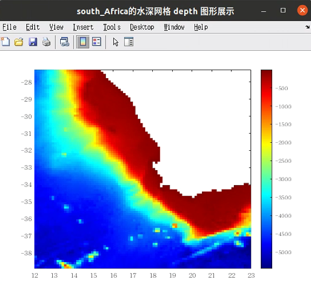 LIM_BATHY = 0.4 LIM_BATHY = 0.4 |
 LIM_BATHY = 0.4 LIM_BATHY = 0.4 |
 LIM_BATHY = 0 LIM_BATHY = 0 |
 LIM_BATHY = 0 LIM_BATHY = 0 |
 LIM_BATHY = 1 LIM_BATHY = 1 |
 LIM_BATHY = 1 LIM_BATHY = 1 |
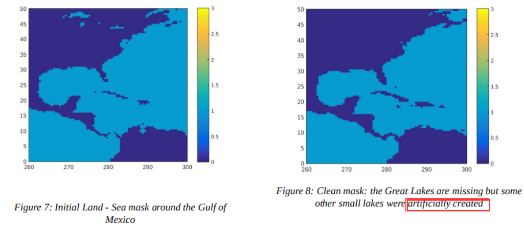
LIM_VAL 和 OFFSET 的改变对 m2 的影响不大,这是因为此区域没有考虑湖泊因素。
OFFSET 设置成太大,运行时间会很长。
在我们的案例中,这并没有导致明显可见的变化,但如果在考虑的网格中存在一些湖泊,它们现在就已经消失了(如下图)。因此,在试图使用这个软件来创建湖泊的网格时,需要谨慎。
另外,这一步可能会出现,局部区域很多
wet单元转变成dry单元从而形成假的湖泊(如下图),下一步就考虑去除这个假的湖泊。
06~~清除海陆掩码 m2中的 不需要的水体,得到海陆掩码 m4(LAKE_TOL, IS_GLOBAL)
掩模的清理工作仍未完成。根据网格的情况,clean_mask()函数可能会有人为生成的
假的湖泊(与水体主体不相连的孤立的wet单元)。这通常是由于<font color='red'>网格分辨率不够精细,无法充分解决海陆边缘问题</font>。这不是南非网格的情况,但在Erreur : source de la référence non trouvée中,你有一个网格的例子,其中有人工生成的假的湖泊。清除
假的湖泊,其实就是清除不需要的水体的一种体现。
%%	清除m2中不需要水体的参数
LAKE_TOL = 100;		%决定对应于某一特定水体的所有wet单元是否应该被标记为 dry的Tolerance value。
					%如果LAKE_TOL > 0,所有水体的wet单元总数小于这个值,将被标记为 dry。
					%如果LAKE_TOL = 0,输出和输入掩码不变。
					%如果LAKE_TOL < 0,除了最大的水体外,其他水体都被标记为 dry。
IS_GLOBAL = 0;		%全球网格的标志设置为1,否则为0。决定单元格是否环绕经度。


%%	清除m2中不需要的水体
[m4,mask_map] = remove_lake(m2,LAKE_TOL,IS_GLOBAL);
					%m4是修改后的海陆掩码;
					%mask_map是为不同水体提供唯一ID的二维数组;
%	清除m2不需要水体的海陆掩码m4的图形展示
figure('NumberTitle','off','Name',strcat(area,'清除m2不需要水体的海陆掩码m4的图形展示'),'Color','w');
pcolor(lon,lat,m4);shading flat;caxis([0 3]);colorbar
%	海陆掩码m2不同水体的图形展示
figure('NumberTitle','off','Name',strcat(area,'海陆掩码m2不同水体的图形展示'),'Color','w');
pcolor(lon,lat,mask_map);shading flat;caxis([-1 6]);colorbar |
 |
在我们的例子中,应用
remove_lake函数后,掩码m2和掩码m4之间没有什么变化,因为m2中只有一个水体。
如果我们考虑
墨西哥湾周围的区域,我们在前面看到小的湖泊是人为制造出来的假的湖泊(Erreur : source de la référence non trouvée),clean_mask函数的效果要明显得多。在LAKE_TOL=-1的情况下,该函数实际上删除了所有wet单元(除了属于大西洋的单元),如图11所示。这是因为它对应的是最大的水体(见图12)。如果希望保留某个水体,可以在mask_map中获得其ID号,然后用命令行m4(mask_map == ID) = 1将m4中的相应点调回1。

07~~生成障碍物网格(OBSTR_OFFSET, 经纬度问题)
障碍物网格是ww3_grid所需的;
障碍物网格的生成可以只考虑单元格本身的障碍物,考虑一个邻近neighbor的障碍物,或者考虑两个邻近的障碍物;
%%	生成障碍物网格的参数
OBSTR_OFFSET = 1;		%OBSTR_OFFSET是决定是否应该考虑邻近(1)或不考虑(0)的标志,需要两次:
						%一次用于左/下邻居,一次用于右/上邻居。

%%	生成障碍物网格
[sx1,sy1] = create_obstr(lon,lat,b,m4,OBSTR_OFFSET,OBSTR_OFFSET);
%	障碍物网格图形展示
sx1(find(m4==0))=NaN;
sy1(find(m4==0))=NaN;
figure('NumberTitle','off','Name',strcat(area,'障碍物网格sx1的图形展示'),'Color','w');
pcolor(lon,lat,sx1);shading flat;caxis([0 1]); colorbar
figure('NumberTitle','off','Name',strcat(area,'障碍物网格sy1的图形展示'),'Color','w');
pcolor(lon,lat,sy1);shading flat;caxis([0 1]); colorbar
<font color='red'>参数sx1和sx2是什么意思?</font>
 |
 |
与
compute_boundary和split_boundary函数一样,create_obstr需要b作为参数。正如我们之前看到的,b中的经度范围只有0°到360°。这意味着如果你使用etopo2的惯例(经度从-180°到180°),经度数组lon需要临时修改。
08~~保存(depth_scale, obstr_scale)
- 一旦网格被生成,它们需要被保存在ASCII文件中,以后将被ww3_grid读取,以生成二进制模型定义文件。
- 由于ww3_grid允许有一个缩放系数,我们将这些变量保存为整数。
通常,我们把水深数据四舍五入到小数点后第三位,把障碍物的值四舍五入到小数点后第二位。
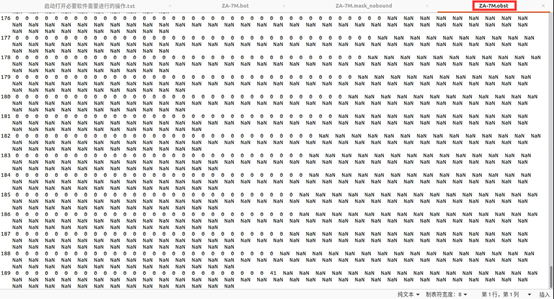
fname='ZA-7M'; %输出文件名称
depth_scale = 1000; %水深的缩放因子
obstr_scale = 100; %障碍物的缩放因子
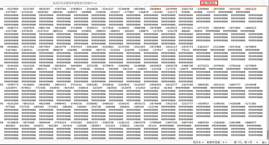
d = round((depth)*depth_scale);
write_ww3file([data_dir,'/',fname,'.bot'],d); %水深数据
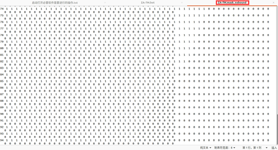
write_ww3file([data_dir,'/',fname,'.mask_nobound'],m4); %陆海掩码网格
d1 = round((sx1)*obstr_scale); %障碍物网格sx1
d2 = round((sy1)*obstr_scale); %障碍物网格sy1
write_ww3obstr([data_dir,'/',fname,'.obst'],d1,d2); %障碍物网格,两个合在一起
write_ww3meta ([data_dir,'/',fname],[nml_dir,'/gridgen.',fname,'.nml'],'RECT',lon,lat,1/depth_scale,1/obstr_scale,1.0);
%meta文件,ASCII编码
write_ww3meta需要在area文件夹下运行;为了与之后的内容相对应,将
south_Africa.m文件改名为south_Africa_ZA_7M.m;
grid创建:南非区域(整体实现,推荐在实际情况中使用)
南非区域很容易手动和逐步创建,因为它有最简单的特征:网格不跨越 格林威治子午线,所有经度都是正数。然而,根据你的水深测量数据集和你要创建的网格,情况可能并不总是这样。一般来说,你必须小心使用 generate_grid、compute_boundary、split_boundary和 create_obstr函数。它们只接受0°到360°的经度,所以对于这些特殊的步骤,你可能要给你的经度阵列的全部或部分增加一个偏移量,甚至把你的网格分成两部分。因此,重复上一节的各个步骤来创建另一个网格可能是一项麻烦的工作。
幸运的是,GRIDGEN工具箱附带了一个通用脚本,可以帮助你以更方便、更安全的方式完成这项工作:只要你给它正确的参数,create_grid函数就会以自动方式为你处理网格的生成。它唯一需要的参数是一个包含所有所需网格信息的 namelist文件。你所要做的就是在这个文件中填入正确的数值–这仍然是一个关键的步骤。
前面的部分是一个逐步的介绍。现在,为了准备你将在另一个教程中实现的多网格运行,我们将使用自动程序来创建第二个南非区域3’分辨率的网格:BENG-3M。所有关于这个网格的信息都存储在 gridgen.BENG-3M.nml 文件中。这是 create_grid函数的唯一参数。
现在,在 area文件夹下创建 south_Africa_BENG_3M.m文件,使用自动工具箱创建这个网格:
%%	因为之前已将 bin 下的函数导入了路径,所以可以调用 GRIDGEN 的所有函数;
create_grid('/home/jincanliu/BaiduNetdiskWorkspace/WaveModel2/work-griden/TUTORIAL_GRIDGEN/namelist/gridgen.BENG-3M.nml')
在这一步之后,你的 data文件夹中应该有4个新的ASCII文件,以 BENG-3M开头。
gridgen.BENG-3M.nml 文件具体内容:
目录和文件名称的路径
$ a. Path to directories and file names-----------------------------------$

$ BIN_DIR : location of matlab scripts
$
$ REF_DIR : location of reference data
$
$ DATA_DIR : input/output grid directory
$
$ FNAME_POLY (???):
$ File with switches for using user-defined polygons.
$ An example file has been provided with the reference data
$ for an existing user-defined polygon database.
$ 0: ignores the polygon | 1: accounts for the polygon.
$ 带有使用用户定义的多边形的开关(switch)的文件。
$ 已经提供了一个示例文件,其中包含现有用户定义的多边形数据库的参考数据。
$ 0:忽略多边形|1:核算多边形。


$
$ FNAME : File name prefix: the routine will create output files
$ fname.bot, fname.mask_rank1, etc.
$
$ FNAMEB : Name of base grid for modmask (if needed)
$
$ BOUND_SELECT(Ⅳ) : Boundary selection :
0 -> manually on the plot
1 -> automatically around the borders
2 -> from a .poly file

&GRID_INIT
BIN_DIR = '../bin'
REF_DIR = '../reference'
DATA_DIR = '../data'
FNAME_POLY = 'user_polygons.flag'
FNAME = 'BENG-3M'
FNAMEB = 'ZA-7M'
BOUND_SELECT = 1
/
水深文件信息
$ b. Information on bathymetry file--------------------------------------$

$ Grid Definition

$ Gridgen is designed to work with curvilinear and/or rectilinear grids. In
$ both cases it expects a 2D array defining the Longitudes (x values) and
$ Latitudes (y values). For curvilinear grids, the user will have to use
$ alternative software to determine these arrays. For rectilinear grids
$ these are determined by the grid domain and desired resolution as shown
$ below
$Gridgen被设计用于处理曲线型和/或直线型网格。
$在这两种情况下,它都希望有一个定义经度(x值)和纬度(y值)的二维数组。
$对于曲线型网格,用户将不得不使用其他软件来确定这些数组(???)。
$对于直线型网格,这些阵列由网格域和所需的分辨率决定,如下图所示。

$ REF_GRID : reference grid source = name of the bathy source file
$ (without '.nc' extension)
$ ref_grid = 'etopo1' -> Etopo1 grid
$ ref_grid = 'etopo2' -> Etopo2 grid
$ ref_grid = 'xyz' -> ASCII .log grid
$ ref_grid = ??? -> user-defined bathymetry file (must match etopo format)
$
$ LONFROM : origin of longitudes
$ lonfrom = -180 -> longitudes from -180 to 180 (etopo2)
$ lonfrom = 0 -> longitudes from 0 to 360 (etopo1)
$
$ XVAR : name of variable defining longitudes in bathy file
$ xvar = 'x' if etopo1
$ xvar = 'lon' if etopo2
$ YVAR : name of variable defining latitudes in bathy file
$ yvar = 'y' if etopo1
$ yvar = 'lat' if etopo2
$ ZVAR : name of variable defining depths in bathy file
$ zvar = 'z' for etopo1 & etopo2 (can be other for user-defined file)

&BATHY_FILE
REF_GRID = 'gebco'
XVAR = 'lon'
YVAR = 'lat'
ZVAR = 'elevation'
LONFROM = -180
/
网格分辨率和边界要求
$ c. Required grid resolution and boundaries---------------------------------$

$ TYPE : rectangular grid 'rect' or curvilinear grid 'curv'
$ DX : resolution in longitudes (°)
$ DY : resolution in latitudes (°)
$ LON_WEST : western boundary
$ LON_EAST : eastern boundary
$
$ if lonfrom = 0 : lon_west & lon_east in [0 ; 360]
$ with possibly lon_west > lon_east
$ if the Greenwich meridian is crossed
$ if lonfrom = -180 : lon_west & lon_east in [-180 ; 180]
$
$ LAT_SOUTH : southern boundary
$ LAT_NORTH : northern boundary
$ lon_south & lon_north in [-90 ; 90]
$
$ IS_GLOBAL(Ⅱ(6)) : set to 1 if the grid is global, else 0
$
$ IS_GLOBALB(Ⅳ): set to 1 if the base grid is global, else 0
$

&OUTGRID
TYPE = 'rect'
DX = 0.05
DY = 0.05
LON_WEST = 16
LON_EAST = 20
LAT_SOUTH = -36
LAT_NORTH = -30
IS_GLOBAL = 0
IS_GLOBALB = 0
/
边界选项
$ d. Boundary options-------------------------------------------------------$

$ BOUNDARY : Option to determine which GSHHS
$ .mat file to load:
$ full = full resolution
$ high = 0.2 km
$ inter = 1 km
$ low = 5 km
$ coarse = 25 km
$
$ READ_BOUNDARY(???) : [0|1] flag to determine if input boundary information
$ needs to be read; boundary data files can be
$ significantly large and need to be read only the first
$ time. So when making multiple grids, the flag can be set
$ to 0 for subsequent grids.
$ (Note : If the workspace is cleared, the boundary data
$ will have to be read again)
$
$ OPT_POLY : [0|1] flag for reading the optional user-defined
$ polygons. Set to 0 if you do not wish to use this option
$
$ MIN_DIST(Ⅱ(3))??? : Used in compute_boundary and in split_boudnary;
$ threshold defining the minimum distance (in °) between
$ the edge of a polygon and the inside/outside boundary.
$ A low value reduces computation time but can raise
$ errors if the grid is too coarse. If the script crashes,
$ consider increasing the value.
$ (Default value in function used to be min_dist = 4)

&GRID_BOUND
BOUNDARY = 'full'    %分别率调整
READ_BOUNDARY = 1
OPT_POLY = 0
MIN_DIST = 4
/
软件中的参数值
$ e. Parameter values used in the software-------------------------------------$

$ DRY_VAL : Depth value set for dry cells (can change as desired)
$ Used in 'generate_grid' and in the making of initial mask
$
$ CUT_OFF : Cut-off depth to distinguish between dry and wet cells.
$ All depths below the cut_off depth are marked wet
$ Used in 'generate_grid'
$ NOTE : If you have accurate boundary polygons, then it is
$ better to have a low value for CUT_OFF, which will make the
$ target bathymetry cell wet even when there are only few wet
$ cells in the base bathymetry. This will then be cleaned up
$ by the polygons in the 'mask cleanup' section. If, on the
$ other, hand you do not intend to use the polygons to define
$ the coastal domains, then you are better off with CUT_OFF = 0.5
$注意:如果你有精确的边界多边形,那么最好将CUT_OFF的值调低,
$这样会使目标测深单元变湿,即使在基本测深中只有少数湿单元。
$然后,这将被 "掩膜清理 "部分中的多边形清理掉。
$另一方面,如果你不打算用多边形来定义沿岸域,那么你最好使用 CUT_OFF = 0.5(???)。
$
$ LIM_BATHY(Ⅱ(2))(???) : Proportion of base bathymetry cells that need to be wet for
$ the target cell to be considered wet.
$需要湿润的基础水深单元的比例,以使目标单元被认为是湿润的。
$
$ LIM_VAL(Ⅱ(5))(???) : Fraction of cell that has to be inside a polygon for the
$ cell to be marked dry
$
$ SPLIT_LIM(Ⅱ(4))(???) : Limit for splitting the polygons; used in split_boundary
$ Rule of thumbs: from 5 to 10 times max(dx,dy)
$
$
$ OFFSET : Additional buffer around the boundary to check if cell is
$ crossing boundary. Should be set to largest grid resolution
$ ie OFFSET = max([dx dy])
$ Used in 'clean_mask'
$
$ LAKE_TOL : Tolerance value that determines if all the wet cells
$ corresponding to a particular wet body should be flagged
$ dry or not.
$ Used in 'remove_lake'
$ if LAKE_TOL > 0 : all water bodies having less than this
$ value of total wet cells will be flagged
$ dry    $例如,如果为100,则弱湖泊(小水体)的单元输为60,则被认为是陆地,即dry
$ if LAKE_TOL = 0 : the output and input masks are unchanged.
$ if LAKE_TOL < 0 : all but the largest water body is flagged
$ dry
$
$ OBSTR_OFFSET : Flag to determine if neighbours should be considered.
$ (0/1 = no/yes)
$ Used in 'create_obstr'

&GRID_PARAM
DRY_VAL = 999999
CUT_OFF = 0
LIM_BATHY = 0.4
LIM_VAL = 0.5
SPLIT_LIM = 0.25
OFFSET = 0.05                    %OFFSET = max([dx dy])
LAKE_TOL = 100
OBSTR_OFFSET = 1
/
添加边界掩码:BENG-3M和ZA-7M
在这个阶段,我们已经为 ZA-7M 和 BENG-3M 网格生成了测深(.bot)、遮蔽(.mask_nobound)、障碍物(.object)和元文件(.meta),所以用户的工作目录应该有这两套网格文件:ZA-7M.*和 BENG-3M.*,另外还有 GLOB-30M.*文件。
<font color='red'>为了正常运行波浪模型</font>,我们必须为 BENG-3M和 ZA-7M<font color='red'>设置边界条件</font>。事实上,这两个网格中的每一个都需要从更粗的网格中接收信息:BENG-3M网格从 ZA-7M网格中接收数据,而后者本身也从 全球网格中获取信息。在本教程的下面部分,我们将看到如何 正确定义这两个网格的边界点。
到目前为止,我们一直在使用 0(陆地 land)和 1(水 water)的掩码值。然而,掩模文件还有两个额外的值可以设置:2(边界点 boundary points)和 3(排除点 excluded points)。[注:排除点选项仅从第3版和更高版本开始提供]。掩码值2和3应该定义内部更细的网格中的边界点,所以 ZA-7M和 BENG-3M网格的掩码需要更新。
首先,让我们为 BENG-3M网格设置边界。它从较粗的 ZA-7M网格获取信息。在这一节中,目标网格(target grid)被定义为精细分辨率的网格(即BENG-3M),其掩码值将被改变以确定边界和排除点,而 基础网格(base grid)被定义为较粗的外部网格(即ZA-7M),目标网格将从其获取信息。这里的目的是定义适当的点,从 基础网格向 目标网格提供边界数据。从第三版开始,WW3允许 (对于更细的网格)在网格内部定义边界点,从而允许 海岸线跟踪网格等功能,尽管我们使用的是常规网格。
目标网格的掩码值会改变,基础网格不变;
GRIDGEN工具箱提供了一个名为 create_boundary的函数,负责在内部掩码中创建边界点。这个函数只需要 gridgen.BENG-3M.nml 文件,更确切地说,是这个文件中的 GRID_INIT名单。GRID_INIT提供了 目标网格和 基础网格的名称(这里分别是 BENG-3M和 ZA-7M),以及你想使用的 边界选择类型的信息。
gridgen.BENG-3M.nml中的GRID_INIT名单$ a. Path to directories and file names-----------------------------------$ $ BIN_DIR : location of matlab scripts $ $ REF_DIR : location of reference data $ $ DATA_DIR : input/output grid directory $ $ FNAME_POLY (???): $ File with switches for using user-defined polygons. $ An example file has been provided with the reference data $ for an existing user-defined polygon database. $ 0: ignores the polygon | 1: accounts for the polygon. $ 带有使用用户定义的多边形的开关(switch)的文件。 $ 已经提供了一个示例文件,其中包含现有用户定义的多边形数据库的参考数据。 $ 0:忽略多边形|1:核算多边形。 $ $ FNAME : File name prefix: the routine will create output files $ fname.bot, fname.mask_rank1, etc. $ $ FNAMEB : Name of base grid for modmask (if needed) $ $ BOUND_SELECT(Ⅳ) : Boundary selection : 0 -> manually on the plot 1 -> automatically around the borders 2 -> from a .poly file &GRID_INIT BIN_DIR = '../bin' REF_DIR = '../reference' DATA_DIR = '../data' FNAME_POLY = 'user_polygons.flag' FNAME = 'BENG-3M' FNAMEB = 'ZA-7M' BOUND_SELECT = 1 /
GRID_INIT中的 SELECT_BOUND参数有3个选项可用:
- SELECT_BOUND = 0:手动选择边界多边形。这将为
目标网格绘制当前掩码(没有边界)。然后你将点击绘图来定义边界多边形的顶点。请注意,多边形必须按逆时针方向定义,并且是封闭的(这使我们能够很容易地识别多边形内部、外部的点)。 - SELECT_BOUND = 1:在
目标网格的边界周围自动选择。如果目的是要使用整个目标网格,这一点特别有用。 - SELECT_BOUND = 2:从一个.poly文件中选择。
不知道为什么 nml 中的是
BOUND_SELECT,文中估计写错了;
现在,你所要做的就是运行这个函数:
create_boundary('~/TUTORIAL_GRIDGEN/namelist/gridgen.BENG-3M.nml');create_boundary函数的输出是:
- 文件
BENG-3M.mask,它对应于内网格的新掩码,考虑到边界的存在(有些值被设置为2和/或3)。 - 文件
BENG-3M.bound和BENG-3M.fullbound,它们提供了边界的位置和名称,以便较粗的网格知道在哪里计算谱(spectra),而较细的网格知道在哪里寻找它。BENG-3M.fullbound文件提供了所有内层网格的边界点,其分辨率为目标网格的分辨率(这在大多数情况下是不需要的),而BENG3M.bound文件则提供了基础网格分辨率的边界点。这只在单网格实施的情况下有用,即粗网格需要提前为细网格处理谱边界。这些文件并不用于多网格的实现。
 BENG-3M.fullbound BENG-3M.fullbound |
 BENG-3M.bound BENG-3M.bound |
在 create_boundary里面,我们使用一个叫做 modify_mask的函数。它将<font color='red'>多边形之外</font>的所有掩码值设置为 目标网格掩码中的 undefined(这些单元在计算中不使用),并沿着多边形确保 目标网格中的每个潜在边界单元,在 基础网格中都有可以接收数据的活动(湿)单元。
对于在 目标网格的边界自动生成多边形(SELECT_BOUND=1),最终掩码由图15给出。图16给出了手动选择多边形(SELECT_BOUND=0)的最终掩码的例子。

请注意,图15中沿着 网格边缘的海中的活动边界单元是2。图16中的 红色单元对应于被排除的点(其中掩码=3),陆地上也有活动的边界点(图16中的右上角部分),这只是手动设置的一个假的边界。
我们已经为 Beng-3M网格添加了边界掩码,同样地,我们为南非网格(South Africa grid)ZA-7M(为Benguela网格提供数据)从 全球网格获得边界信息,你需要为这个网格再运行一次 compute_boundary。这里,目标网格是 ZA-7M,基础网格是 GLOB-30M,定义在 gridgen.ZA-7M.nml文件中。
create_boundary('~/TUTORIAL_GRIDGEN/namelist/gridgen.ZA-7M.nml');注意 : 如果你没有一个
基础网格,你仍然可以通过将基础网格(即GRID_INIT中FNAMEB选项)设置为与你的网格相同的名称来定义活动边界。
由 GRIDGEN得到的 ZA-7M.meta文件创建 WW3的 ww3_grid.nml(2019-附录E)
一旦 GRIDGEN 工具箱生成了所有的网格和边界文件,您必须设置 ww3_grid.nml,WAVEWATCHIII 将使用它来创建模型定义文件 mod_def.ww3。
首先将 ww3_grid.nml 文件从 ww3 模板复制到您的 data文件夹中:
cp /home/jincanliu/BaiduNetdiskWorkspace/WaveModel2/COURS/WAVES-SHORT-COURSE/MODEL/WW3/model/nml/ww3_grid.nml /home/jincanliu/BaiduNetdiskWorkspace/WaveModel2/work-griden/TUTORIAL_GRIDGEN/data/打开 ww3_grid.nml 文件以填写您的网格配置。每个部分都会描述。
第一部分是关于频率和方向的定义。您可以将较低频率降低到取决于您在域上可以预期的最大波周期,我们通常将其设置为 0.0373,对应于 27 秒波周期,在这种情况下,您还必须将频率离散化增加到 32:
&SPECTRUM_NML SPECTRUM%XFR = 1.1 SPECTRUM%FREQ1 = 0.0373 SPECTRUM%NK = 32 SPECTRUM%NTH = 24 /第二部分是关于波的传播,折射和源项的激活。如果您在强流下运行模型,则必须激活波数偏移:
&RUN_NML RUN%FLCX = T RUN%FLCY = T RUN%FLCTH = T RUN%FLSOU = T /第三部分用于将所限定的
模型时间步长。要计算的第一个时间步长是最大 CFL 时间步长,它取决于先前设置为 0.0373Hz 的最低频率 Fmin和最靠近极点的纬度(此处为 -38.9S)沿 x 的最低空间网格分辨率。## dx计算公式 dx = min(reslon * cos(maxlat*Pi/180)*1852*60, reslon * cos(minlat*Pi/180)*1852*60) #reslon对应沿 x 的最低空间网格分辨率,单位为° #maxlat对应北纬度数最大的值,例如90比60大; #minlat对应南纬度数最小的值,例如-90比-60小; ## dx计算 dx = 0.12 * cos(-38.9*3.14/180)*1852* 60 = 2074m提醒:
<font color='red'>1 度 = 60 分钟 // 1 分钟 = 1 英里 // 1 英里 = 1.852 公里</font>。## cfl计算公式 Tcfl = dx / (g / (Fmin*4*Pi) ), 常数 Pi=3,14 和 g=9.8m/s²; ## cfl计算 Tcfl = 2074 / (9.8 / (0.0373*4*3.14) ) = 99s ## 最大cfl计算 maxTcfl ~= 90% Tcfl = 90s ## 最大全局时间步长计算 # 知道maxTcfl,最大全局时间步长通常设置为3倍, # 最多可以设置6倍,节省计算时间,尽管精度损失更大; Tglob = 3*maxTcfl = 3*90 = 270s ## 折射时间步长计算 # 折射时间步长取决于网格上风或流的强度,通常设置为全局的 1/6 时间步长, # 但在强风或强风的情况下可以减少到 1/10: Tref = Tglob / 6 = 270 / 6 = 45s ## 最小源项时间步长通常定义在 1 到 10 秒之间 Tsrc = 1snml中的参数设置(与官方文档给的不太一样)! -------------------------------------------------------------------- ! ! Define the timesteps parameterization via TIMESTEPS_NML namelist ! ! * It is highly recommended to set up time steps which are multiple ! between them. ! ! * The first time step to calculate is the maximum CFL time step ! which depend on the lowest frequency FREQ1 previously set up and the ! lowest spatial grid resolution in meters DXY. ! reminder : 1 degree=60minutes // 1minute=1mile // 1mile=1.852km ! The formula for the CFL time is : ! Tcfl = DXY / (G / (FREQ1*4*Pi) ) with the constants Pi=3,14 and G=9.8m/s²; ! DTXY ~= 90% Tcfl ! DTMAX ~= 3 * DTXY (maximum global time step limit) ! ! * The refraction time step depends on how strong can be the current velocities ! on your grid : ! DTKTH ~= DTMAX / 2 ! in case of no or light current velocities ! DTKTH ~= DTMAX / 10 ! in case of strong current velocities ! ! * The source terms time step is usually defined between 5s and 60s. ! A common value is 10s. ! DTMIN ~= 10 ! ! * namelist must be terminated with / ! * definitions & defaults: ! TIMESTEPS%DTMAX = 0. ! maximum global time step (s) ! TIMESTEPS%DTXY = 0. ! maximum CFL time step for x-y (s) ! TIMESTEPS%DTKTH = 0. ! maximum CFL time step for k-th (s) ! TIMESTEPS%DTMIN = 0. ! minimum source term time step (s) ! -------------------------------------------------------------------- ! &TIMESTEPS_NML TIMESTEPS%DTMAX = 270. TIMESTEPS%DTXY = 90. TIMESTEPS%DTKTH = 45. TIMESTEPS%DTMIN = 1. /第四部分为网格信息,它通常是域名其次是空间分辨率,它不能超过30个字符。
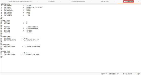
&GRID_NML
 GRID%NAME = 'ZA-7M'
 GRID%NML = 'namelists_ZA-7M.nml'
 GRID%TYPE = 'RECT'
 GRID%COORD = 'SPHE'
 GRID%CLOS = 'NONE'
 GRID%ZLIM = -0.10
 GRID%DMIN = 2.5
/
文件
namelists_ZA-7M.nml包含与用于编译模型的开关对应的名称列表的定义。对于第一次测试,您可以将其留空以使用默认值。在任何情况下,它都必须以END OF NAMELISTS行结束。下一部分为直线网格的定义,它包含的点数,网格分辨率和网格的西南角;
! -------------------------------------------------------------------- ! ! Define the rectilinear grid type via RECT_NML namelist ! - only for RECT grids - ! ! * The minimum grid size is 3x3. ! ! * If the grid increments SX and SY are given in minutes of arc, the scaling ! factor SF must be set to 60. to provide an increment factor in degree. ! ! * If CSTRG='SMPL', then SX is forced to 360/NX. ! ! * value <= value_read / scale_fac ! ! * namelist must be terminated with / ! * definitions & defaults: ! RECT%NX = 0 ! number of points along x-axis ! RECT%NY = 0 ! number of points along y-axis ! ! RECT%SX = 0. ! grid increment along x-axis ! RECT%SY = 0. ! grid increment along y-axis ! RECT%SF = 1. ! scaling division factor for x-y axis ! ! RECT%X0 = 0. ! x-coordinate of lower-left corner (deg) ! RECT%Y0 = 0. ! y-coordinate of lower-left corner (deg) ! RECT%SF0 = 1. ! scaling division factor for x0,y0 coord ! -------------------------------------------------------------------- ! &RECT_NML RECT%NX = 89 RECT%NY = 94 ! RECT%SX = 0.12 RECT%SY = 0.12 RECT%X0 = 12.0000 RECT%Y0 = -38.9000 /最后部分为depth文件,mask文件,obstruction文件;
! -------------------------------------------------------------------- !
! Define the depth to preprocess via DEPTH_NML namelist
! - for RECT and CURV grids -
!
! * if no obstruction subgrid, need to set &MISC FLAGTR = 0
!
! * The depth value must have negative values under the mean sea level
!
! * value <= value_read * scale_fac
!
! * IDLA : Layout indicator :
!                  1   : Read line-by-line bottom to top.  (default)
!                  2   : Like 1, single read statement.
!                  3   : Read line-by-line top to bottom.
!                  4   : Like 3, single read statement.
! * IDFM : format indicator :
!                  1   : Free format.  (default)
!                  2   : Fixed format.
!                  3   : Unformatted.
! * FORMAT : element format to read :
!               '(....)'  : auto detected  (default)
!               '(f10.6)' : float type
!
! * Example :
!      IDF  SF     IDLA  IDFM   FORMAT    FILENAME
!      50   0.001  1     1     '(....)'  'GLOB-30M.bot'
!
! * namelist must be terminated with /
! * definitions & defaults:
!     DEPTH%SF             = 1.       ! scale factor
!     DEPTH%FILENAME       = 'unset'  ! filename
!     DEPTH%IDF            = 50       ! file unit number
!     DEPTH%IDLA           = 1        ! layout indicator
!     DEPTH%IDFM           = 1        ! format indicator
!     DEPTH%FORMAT         = '(....)' ! formatted read format
! -------------------------------------------------------------------- !
&DEPTH_NML
 DEPTH%SF = 0.00
 DEPTH%FILENAME = '../data/ZA-7M.bot'
/
! -------------------------------------------------------------------- ! ! Define the point status map via MASK_NML namelist ! - only for RECT and CURV grids - ! ! * If no mask defined, INBOUND can be used to set active boundaries ! ! * IDLA : Layout indicator : ! 1 : Read line-by-line bottom to top. (default) ! 2 : Like 1, single read statement. ! 3 : Read line-by-line top to bottom. ! 4 : Like 3, single read statement. ! * IDFM : format indicator : ! 1 : Free format. (default) ! 2 : Fixed format. ! 3 : Unformatted. ! * FORMAT : element format to read : ! '(....)' : auto detected (default) ! '(f10.6)' : float type ! ! * Example : ! IDF IDLA IDFM FORMAT FILENAME ! 60 1 1 '(....)' 'GLOB-30M.mask' ! ! * The legend for the input map is : ! -2 : Excluded boundary point (covered by ice) ! -1 : Excluded sea point (covered by ice) ! 0 : Excluded land point ! 1 : Sea point ! 2 : Active boundary point ! 3 : Excluded grid point ! 7 : Ice point ! ! * namelist must be terminated with / ! * definitions & defaults: ! MASK%FILENAME = 'unset' ! filename ! MASK%IDF = 60 ! file unit number ! MASK%IDLA = 1 ! layout indicator ! MASK%IDFM = 1 ! format indicator ! MASK%FORMAT = '(....)' ! formatted read format ! -------------------------------------------------------------------- ! &MASK_NML MASK%FILENAME = '../data/ZA-7M.mask' /! -------------------------------------------------------------------- ! ! Define the obstruction map via OBST_NML namelist ! - only for RECT and CURV grids - ! ! * only used if &MISC FLAGTR = 1 in param.nml ! (transparencies at cell boundaries) ! or if &MISC FLAGTR = 2 in param.nml ! (transparencies at cell centers) ! or if &MISC FLAGTR = 3 in param.nml ! (transparencies at cell boundaries with cont. ice) ! or if &MISC FLAGTR = 4 in param.nml ! (transparencies at cell centers with cont. ice) ! ! * value <= value_read * scale_fac ! ! * IDLA : Layout indicator : ! 1 : Read line-by-line bottom to top. (default) ! 2 : Like 1, single read statement. ! 3 : Read line-by-line top to bottom. ! 4 : Like 3, single read statement. ! * IDFM : format indicator : ! 1 : Free format. (default) ! 2 : Fixed format. ! 3 : Unformatted. ! * FORMAT : element format to read : ! '(....)' : auto detected (default) ! '(f10.6)' : float type ! ! * Example : ! IDF SF IDLA IDFM FORMAT FILENAME ! 70 0.0001 1 1 '(....)' 'GLOB-30M.obst' ! ! * If the file unit number equals 10, then the data is read from this ! file. The data must follow the above record. No comment lines are ! allowed within the data input. ! ! * In the case of unstructured grids, no obstruction file can be added ! ! * namelist must be terminated with / ! * definitions & defaults: ! OBST%SF = 1. ! scale factor ! OBST%FILENAME = 'unset' ! filename ! OBST%IDF = 70 ! file unit number ! OBST%IDLA = 1 ! layout indicator ! OBST%IDFM = 1 ! format indicator ! OBST%FORMAT = '(....)' ! formatted read format ! -------------------------------------------------------------------- ! &OBST_NML OBST%SF = 0.01 OBST%FILENAME = '../data/ZA-7M.obst' /